
AT89C51
------------------------------------------------------------------------------------------------------------------------
Features :
• Compatible with MCS-51™ Products
• 4K Bytes of In-System Reprogrammable Flash Memory
– Endurance: 1,000 Write/Erase Cycles
• Fully Static Operation: 0 Hz to 24 MHz
• Three-level Program Memory Lock
• 128 x 8-bit Internal RAM
• 32 Programmable I/O Lines
• Two 16-bit Timer/Counters
• Six Interrupt Sources
• Programmable Serial Channel
• Low-power Idle and Power-down Modes
Description :
The AT89C51 is a low-power, high-performance CMOS 8-bit microcomputer with 4K bytes of Flash programmable and erasable read only memory (PEROM). The device is manufactured using Atmel’s high-density nonvolatile memory technology and is compatible with the industry-standard MCS-51 instruction set and pinout. The on-chip Flash allows the program memory to be reprogrammed in-system or by a conventional nonvolatile memory programmer. By combining a versatile 8-bit CPU with Flash on a monolithic chip, the Atmel AT89C51 is a powerful microcomputer which provides a highly-flexible and cost-effective solution to many embedded control applications.
PIN Diagram :

------------------------------------------------------------------------------------------------------------------------------------------
Serial LEDs using AT89c51:
connecting LEDS to P2 pins and SWITCHES to P1 pins.
#include<reg51.h>
sfr leds=0xA0;
sfr SW=0x90;
unsigned int x;
int main ()
{
while(1)
{
if(SW==0xFE)
{
leds=0x08 ; //"1000"
for( x=0;x<20000;x++); // providing some random delay
leds=0x04; //"0100"
for( x=0;x<20000;x++);
leds=0x02; //"0010"
for( x=0;x<20000;x++);
leds=0x01; //"0001"
for( x=0;x<20000;x++);
}
else if(SW==0xFD)
{
leds=0x01; //"0001"
for( x=0;x<20000;x++);
leds=0x02; //"0010"
for( x=0;x<20000;x++);
leds=0x04; //"0100"
for( x=0;x<20000;x++);
leds=0x08; //"1000"
for( x=0;x<20000;x++);
}
else if(SW==0xFB)
{
leds=0x09; //"1001"
for( x=0;x<20000;x++);
leds=0x06; //"0110"
for( x=0;x<20000;x++);
}
else if(SW==0xF7)
{
leds=0x06; //"0110"
for( x=0;x<20000;x++);
leds=0x09; //"1001"
for( x=0;x<20000;x++);
}
else
leds=0x00;
}
}
Reslut: to see the output

.
Delay using Timers: Gives Square Wave output
Providing Delay using internal timers of AT89c51. We are generating a pulse wave having 250ms ON time and 250ms OFF time. microcontroller clock time is 1.085us.
25ms / 1.085us = 23041 = A5FE in hex
25ms x 10 = 250ms
#include<reg51.h>
void T0delay(void); // delay function
sbit Mybit=P2^0; // output port
void main(void)
{
unsigned char x;
while(1)
{
Mybit= ~Mybit; // inverter
for(x=0;x<10;x++)
T0delay();
}
}
void T0delay(void)
{
TMOD=0x01; // selecting timer-0 mode-1
TL0=0xFE; // count starts at A5FE
TH0=0xA5;
TR0=1; // timer-0 run
while(TF0==0); //wait until timer-0 flag overflow
TR0=0; // then stop timer-0
TF0=0; // reset the overflow flag
}
Result: to see output

Result:

.
Pulse Width Modulated signal (PWM) using Timers:
PWM signals have many application in real world applications example to control the speed of the DC motor. Here we are generating a PWM signal having 250ms , 125ms and 50ms pulse widths.
#include<reg51.h>
void T0delay(void);
sbit Mybit=P1^0; // output PWM port
void main(void)
{
unsigned char x;
while(1)
{
Mybit=1;
for(x=0;x<10;x++) // generating 250ms delay for ON time
{
T0delay();
}
Mybit=0;
for(x=0;x<10;x++) // generating 250ms delay for OFF time
{
T0delay();
}
Mybit=1;
for(x=0;x<5;x++) // generating 125ms delay for ON time
{
T0delay();
}
Mybit=0;
for(x=0;x<5;x++) // generating 125ms delay for OFF time
{
T0delay();
}
Mybit=1;
for(x=0;x<2;x++) // generating 50ms delay for ON time
{
T0delay();
}
Mybit=0;
for(x=0;x<2;x++) // generating 50ms delay for OFF time
{
T0delay();
}
}
}
// 25ms delay function
void T0delay(void)
{
TMOD=0X01; // timer-0 mode-1
TL0=0xFE;
TH0=0xA5;
TR0=1;
while(TF0==0);
TR0=0;
TF0=0;
}
Result: to see the output


.
Serial communication:
Transmit the following strings when the
corresponding switch is pressed
“EMBEDDED SYSTEMS” ; “ EMBEDDED PROGRAMMING” ; “ASSEMBLY PROGRAMMING”; #include<reg51.h>
sbit sw1=P2^0; // switchs connecting port-2 lower pins 0,1,2
sbit sw2=P2^1;
sbit sw3=P2^2;
void Transmit(unsigned char ); // function initialization
void main()
{
unsigned char x;
unsigned char name1[ ]="Embedded systems";
unsigned char name2[ ]="Embedded programming";
unsigned char name3[ ]="Assembly programming";
TMOD=0x20; // timer-1 mode-2
TH1=0xFD; // preset value FD
SCON=0x50; //Serial control 9600 baud rate selection
TR1=1; // run timer-1
while(1)
{
if(sw1==0) // check if switch 1 is pressed
{
for(x=0;x<=16;x++) // transmitting 17 characters to serial port
{
Transmit(name1[x]);
}
}
if(sw2==0) // check if switch 2 is pressed
{
for(x=0;x<=20;x++) // transmitting 21 characters to the serial port
{
Transmit(name2[x]);
}
}
if(sw3==0) // check if switch 3 is pressed
{
for(x=0;x<=20;x++) // transmitting 21 characters to the serial port
{
Transmit(name3[x]);
}
}
}
}
// serial port declaration
void Transmit(unsigned char i)
{
SBUF=i;
while(TI==0); // wait until serial Transmit interrupt flag overflow
TI=0;
}
Result: to see the output


Interfacing 16x2 LCD Display:
. Displaying “Embedded Systems” in 16x2 LCD display
#include<reg51.h>
sfr ldata=0x90;
sbit rs=P2^0; // LCD reset
sbit rw=P2^1; // read/write control
sbit en=P2^2; // LCD r/w enable
void Tdelay(unsigned int ); // functions initializaion
void lcdcmd(unsigned char );
void lcd_data(unsigned char );
void lcd_init(void);
void lcd_display(unsigned char *c );
int main( )
{
while(1){
lcd_init( );
lcd_display("Embedded Systems");
}
}
void Tdelay(unsigned int ms) // providing some delay
{
unsigned int i,j;
for(i=0;i<ms;i++)
for(j=0;j<1275;j++);
}
void lcd_init( void)
{
lcdcmd(0x38);
Tdelay(25);
lcdcmd(0x0F); //display on , cursor blinking
Tdelay(25);
lcdcmd(0x06); // cursor increment
Tdelay(25);
lcdcmd(0x80); // start at row-1
Tdelay(25);
lcdcmd(0x01); // clear screen
Tdelay(10);
}
void lcdcmd(unsigned char cvalue ) // LCD in command mode opearaion
{
ldata=cvalue;
rs=0;
rw=0;
en=1;
Tdelay(1);
en=0;
}
void lcd_display(unsigned char *dvalue)
{
unsigned int x;
for(x=0;dvalue[x]!=0;x++)
{
lcd_data(dvalue[x]);
Tdelay(10);
}
}
void lcd_data(unsigned char dvalue) // LCD in data mode operation
{
ldata=dvalue;
rs=1;
rw=0;
en=1;
Tdelay(1);
en=0;
}
Result: to see the output

.
Displaying Messages in LCD:
#include<reg51.h>
sfr ldata=0x90;
sbit rs=P2^0;
sbit rw=P2^1;
sbit en=P2^2;
sbit sw1=P3^0;
sbit sw2=P3^1;
sbit sw3=P3^2;
void Tdelay(unsigned int );
void lcdcmd(unsigned char );
void lcd_data(unsigned char );
void lcd_init(void);
void lcd_display(unsigned char *c );
int main( )
{
while(1){
lcd_init( );
if (sw1==0)
lcd_display("Embedded Systems");
if (sw2==0)
lcd_display("Electronics");
if(sw3==0)
lcd_display("Embedded programming");
}
}
void Tdelay(unsigned int ms)
{
unsigned int i,j;
for(i=0;i<ms;i++)
for(j=0;j<1275;j++);
}
void lcd_init( void)
{
lcdcmd(0x38);
Tdelay(25);
lcdcmd(0x0F); //display on , cursor blinking
Tdelay(25);
lcdcmd(0x06); // cursor increment
Tdelay(25);
lcdcmd(0x80); // start at row-1
Tdelay(25);
lcdcmd(0x01); // clear screen
Tdelay(10);
}
void lcdcmd(unsigned char cvalue ) // lcd in command mode
{
ldata=cvalue;
rs=0;
rw=0;
en=1;
Tdelay(1);
en=0;
}
void lcd_display(unsigned char *dvalue)
{
unsigned int x;
for(x=0;dvalue[x]!=0;x++)
{
lcd_data(dvalue[x]);
Tdelay(10);
}
}
void lcd_data(unsigned char dvalue) // lcd in data mode
{
ldata=dvalue;
rs=1;
rw=0;
en=1;
Tdelay(1);
en=0;
}
Result: to see the output

.
DC motor Controlling :
Controlling 2 motors in
both forward, reverse and one forward one reverse operation according to the 4
input pins. When input is 1110=both in forward;1101=both in reverse;1011=left
one forward right one stop; 0111=left one stop and right one forward.
MicroCode:
#include<reg51.h>
sfr sw=0x90;
sbit EN1=P2^0;
sbit EN2=P3^0;
sbit MTR1_0=P2^1;
sbit MTR1_1=P2^2;
sbit MTR2_0=P3^1;
sbit MTR2_1=P3^2;
void main( )
{
EN1=0;
MTR1_0=0;
MTR1_1=0;
EN2=0;
MTR2_0=0;
MTR2_1=0;
while(1)
{
EN1=1;
EN2=1;
if(sw==0xFE)
{
MTR1_0=0;
MTR1_1=1;
MTR2_0=0;
MTR2_1=1;
}
else if(sw==0xFD)
{
MTR1_0=1;
MTR1_1=0;
MTR2_0=1;
MTR2_1=0;
}
else if(sw==0xFB)
{
MTR1_0=0;
MTR1_1=1;
MTR2_0=0;
MTR2_1=0;
}
else if(sw==0xF7)
{
MTR1_0=0;
MTR1_1=0;
MTR2_0=0;
MTR2_1=1;
}
else
{
MTR1_0=0;
MTR1_1=0;
MTR2_0=0;
MTR2_1=0;
}
}
}
Result: to see the output

4x4 KeyPad interfacing:
//----- reading the char/number from the keyboard----//
#include<reg51.h>
#define ROW P1 // assigning Port1 to ROW
#define COL P2 // assigning port2 to COL
void msdelay(unsigned int value);
void sertx(unsigned char );
unsigned char dat[4][4]={'0','1','2','3', // keypad read data
'4','5','6','7',
'8','9','A','B',
'C','D','E','F'};
void main()
{
unsigned char colloc,rowloc; // initializing column and row locations
TMOD=0x20; // timer -2 mode-2
TH1=0xFD; // preset FD
SCON=0x50; // serial control reg. 9600 baudrate
TR1=1; // timer-1 start
COL=0xFF; // make column pins input
while(1)
{
do
{
ROW=0x00; // write "00000000" to ROW
colloc=COL; // read column input
colloc&=0x0F; // hide higher nibble
}while(colloc!=0x0f); //check whether any change in column pins
do
{
do
{
msdelay(20);
colloc=COL;
colloc&=0x0F;
}while(colloc==0x0F);
msdelay(20); // check column after 20ms
colloc=COL; // it is for accuracy if there is any random spike it can ignore
colloc&=0x0F;
}while(colloc==0x0F);
while(1)
{
ROW=0xFE; // write "1111_1110" on to ROW
colloc=COL;
colloc&=0x0F;
if(colloc!=0x0F) // if there is a change in column/button pressed
{
rowloc=0;
break;
}
ROW=0xFD; // writing "1111_1101" onto the ROW
colloc=COL;
colloc&=0x0F;
if(colloc!=0x0F) // if there is a change in column/button pressed
{
rowloc=1;
break;
}
ROW=0xFB; // writing "1111_1011" onto the ROW
colloc=COL;
colloc&=0x0F;
if(colloc!=0x0F) // if button pressed / change in column
{
rowloc=2;
break;
}
ROW=0xF7; // writing "1111_0111" onto ROW
colloc=COL;
colloc&=0x0F;
if(colloc!=0x0F) // if button pressed/change in column
{
rowloc=3;
break;
}
}
if(colloc==0x0E)
sertx( dat[rowloc][0]);
if(colloc==0x0D)
sertx(dat[rowloc][1]);
if(colloc==0x0B)
sertx(dat[rowloc][2]);
if(colloc==0x07)
sertx(dat[rowloc][3]);
}
}
void sertx(unsigned char x)
{
SBUF=x;
while(TI==0);
TI=0;
}
void msdelay(unsigned int value)
{
unsigned int i,j;
for(j=0;j<value;j++)
for(i=0;i<100;i++) ;
}
Result: to see the output


Change UserID and Password using 8051:
Here is the one example showing how to change Predefined "UserID" and "Password" manually by user. If we want to change userID or password, it will take inputs from the keypad two times for confirmation. If the two inputs are matched then one of them will be assigned to the predefined one , otherwise it will display "not matched" inputs and jumps to main menu. The following flow chart describes how it works
Here is the one example showing how to change Predefined "UserID" and "Password" manually by user. If we want to change userID or password, it will take inputs from the keypad two times for confirmation. If the two inputs are matched then one of them will be assigned to the predefined one , otherwise it will display "not matched" inputs and jumps to main menu. The following flow chart describes how it works

click here to see the output
click here to download the code
It is showing initial user ID and Password when the power is ON.


click here to download the code
It is showing initial user ID and Password when the power is ON.
It is showing new UserID and Password when the user changed successfully
.
Smart Energy Meter Using 8051:
This is just a prototype of original meter having some features.
This is just a prototype of original meter having some features.
conventional
analog energy meters indicates the meter reading by scrolling down the
mechanical number plates. It will not show daily power consumption and
cost/unit to the consumer. This is a prototype of Smart Energy meter it
indicates the meter reading and cost/unit and also it can send the same
information to the power grid. This is developed using AT89c51
microcontroller.
Features:
> Security UserID and Password
> Read Units anytime and price/unit
> send no.of Units to grid
> we can change userID and Password
> get back to previous menu
click hereto download code
Here is the functional tree chart

Features:
> Security UserID and Password
> Read Units anytime and price/unit
> send no.of Units to grid
> we can change userID and Password
> get back to previous menu
click hereto download code
Here is the functional tree chart
high level Flow chart: it gives behavioral working model of the meter

Results: Click here to see the video how it works
When user selected read units : displaying no.of units and price/unit

 NOTE: meter
readings are calculated by IR LED and PhotoDetector. In between the IR
LED and PhotoDetector there will be a rotating magnetic coil of a
conventional meter. But here we replaced it with one push button
connected to the 555 timer(Monostable multivibrator), because we can't
represent them here.
NOTE: meter
readings are calculated by IR LED and PhotoDetector. In between the IR
LED and PhotoDetector there will be a rotating magnetic coil of a
conventional meter. But here we replaced it with one push button
connected to the 555 timer(Monostable multivibrator), because we can't
represent them here.
.
Password based Door Locking System:
This is a 8051 based security project, we can lock and unlock the door electronically. Electronic door locking systems are used in Bank lockers, home lockers, main doors and prison etc.,


.jpg)
.jpg)
Line follower Robot using 8051
This robot can follow black line on the floor. It is designed using micro controller and IR sensors.


.
1.RF remote controlled home loadsResults: Click here to see the video how it works
When user selected read units : displaying no.of units and price/unit
when user selected send to grid : it sent ID and no.of units consumed by the user
.
Password based Door Locking System:
This is a 8051 based security project, we can lock and unlock the door electronically. Electronic door locking systems are used in Bank lockers, home lockers, main doors and prison etc.,
Working: When
we give correct UserID and Password then only we can INLOCK and LOCK
the door otherwise we can't operate it. If we entered correct userID and
password it will show authenticated message on LCD screen otherwise
Invalid userID or Access Denide. Then you can select one of the option
LOCK DOOR and UNLOCK DOOR.
Here is the functional flow chart
to download C-code
Here we are showing how door can be locked and unlocked mechanically and electrically with mechanical body of the door
Here we are showing how door can be locked and unlocked mechanically and electrically with mechanical body of the door
case'1': when the door is locked
case'2':When the door is unlocked
NOTE: I haven't connected any motor driver here, but practically we can interconnect opto-coupler or motor driver H-bridge.
.
Automatic Train Gate controlling / Metro Train Indication
.
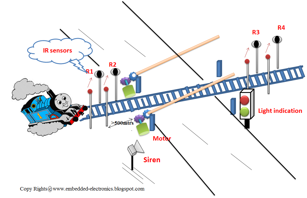
Automatic Train Gate controlling / Metro Train Indication
This Embedded System is designed to control the train junction Gates automatically when train passes across this junction. Here we arrange two IR sensors before the junction ( distance > 500mtrs from Gate junction) and also two IR sensors after the junction (distance > 500mtrs from Gate junction). The IR sensors which are before the junction will indicate that the train is coming near to the junction and the IR sensors which are after the junction will indicate that the train has passed away the junction.
The pictorial arrangement of the system is shown here
when train comes in between the 2 IR sensors the output of both the photodetectors will become logic - '1'. Then the system will send logic high to the Siren, Red light will glow , green light will turn off and the Gate will close.
Here is the simple flow chart showing its operation
Case'1': When train is coming near to the junction
Case '2': When train passed away the junction
NOTE:
Here we connected single servo motor b'coz it is a prototype. but in real time we will use two servo motors, and also here the Siren is replaced by Yellow color LED and IR sensors are replaced by optocouplers.
.
Automatic Room bulb and fan controlling:
This system will control the room light and fan by taking inputs as person count, room light intensity and room temperature.
Working: When there is no person entered in to room then person count will
become zero and then it will not check intensity and temperature, so
that bulb and fan will be in OFF mode. If a person enters into a room then the person count will be increased by '1' and if person exits a room then person count will decrease. If person count is greater than zero then it will check intensity and temperature. If the room intensity is less than the threshold then the bulb will glow otherwise will be in OFF mode only and if the room temperature exceeds the threshold temperature then the fan will start moving otherwise will be in OFF mode only.
Pictorial view of system arrangement
Here is the main flow chart
This flow chart is used to indicate person count, but in practical we dont need to implement this part
Output Results:
case'1': when there is not person in the room
case'2': when there are two persons in the room, room condition the intensity is less and temperature is greater than the threshold temperature
NOTE:
1. Threshold values may be different in practical
2. push buttons will be replaced by IR sensor network in practical
3. person count LEDs are not needed in practical
.Line follower Robot using 8051
This robot can follow black line on the floor. It is designed using micro controller and IR sensors.
Here is the simple schematic diagram
case'1': when right motor crossed black line
case'2': normal operation
IR sensor operation
push buttons should be replaced by IR senors and comparator circuits
.
Coal mine detection Robot:
It is mandatory to check the coal mine weather conditions prior to workers entry. If the weather conditions are normal then workers can enter , otherwise they will not go inside the mine. To check the weather conditions all over the mine we will send one robot which will monitor CO (carbon monoxide) in the mine, temperature and light intensity in the mine. After reading each parameter it will compare with threshold readings and produces output depending the readings taken. This robot is a obstacle avoidance robot, it uses IR sensors to control its movement in the mine.
here is the flow chart

to download C-code
to see video output
Schematic Diagram:
case'1': when the light intensity is less in the mine
pulse width to the light is 0.1sec. and obstacle detected on left side. robot moving to right side
 case'2': when light intensity is less, high temperature and CO gas exceeded in the mine
pulse width to the light is varying 0.1s, 0.25s and 0.5 sec to indicate 3 parameters are not in normal condition. and no obstacle detected
 NOTE:
NOTE:
push button at P1.3 has to be replaced by CO Gas sensor,
push buttons at P1.4 and P1.4 are to be replaced by IR sensors.
Green LED will be replaced by Buzzer.
Threshold values may vary in practical
.
Automatic Car Parking Indicator:
to see video output
Schematic Diagram:
case'1': when the light intensity is less in the mine
pulse width to the light is 0.1sec. and obstacle detected on left side. robot moving to right side
pulse width to the light is varying 0.1s, 0.25s and 0.5 sec to indicate 3 parameters are not in normal condition. and no obstacle detected
push button at P1.3 has to be replaced by CO Gas sensor,
push buttons at P1.4 and P1.4 are to be replaced by IR sensors.
Green LED will be replaced by Buzzer.
Threshold values may vary in practical
.
Automatic Car Parking Indicator:
This system will indicate empty car parking slots at the entry level. Car parking at shopping malls and markets is a big issue, is creating traffic jam. To avoid this we will use this system to indicate empty slots and filled slots, so that a car owner can directly take his car to that particular empty slot. we will indicate the slot state by LEDs and also in LCD screen. we will use IR sensors to sense the presence of car in the slot.
Working: when a car enter into a empty slot the photo detector output will become '1', this will change the state of the slot to filled, otherwise it is remained in empty state only. like wise all the slots are detected by IR sensors.
Here is the functional flow chart
Schematic Diagram:
case'1': when all the slots are empty
all the LEDs are glowing and slot states are displayed in LCD
here LED ON means slot empty; and LED OFF means slot filled
case'2': when 1st and 2nd slots are filled
1st and 2nd LEDs are glowing and the same thing is displayed in LCD
NOTE:
LEDs are to be replaced by IR sensors and comparators
As I already mentioned earlier the basic need to build an embedded system is the desired application. First you decide what application you want. I chose my application that is to build a system that can control the home loads through remote. I decided to do that project strongly, and what is next step ? That Is our required functionality. Here I decided to control four home loads that might be fan, lights, TV, etc., .
Then draw the basic block diagram of your application

I built my block diagram as I required. Go through the required components, I chose
Transmitter Part:-
Ø Since I am using wireless communication I required one receiver transmitter pair. Here am using RF Txr &Rxr pair which will be operated in 433MHz frequency band. These pair can operate in limited area up to 80mtrs. Instead we can use IR transmission also but it can operate in line –of-sight conditions.
Ø To operate the four loads I can choose 4-push buttons at the transmitter side. Since wireless communication is a serial communication we can’t transmit parallel data. So we require a Encoder which can convert parallel data to serial data. Here I chose HT12E encoder. With this I completed the basic requirements to build transmitter part. The total circuit will be shown later.
Receiver Part:-
Receiver Part:-
Ø Encoded data will be received through the RF receiver. It has to convert from serial data to parallel data, for that we need to use the compatible Decoder. I chose HT12D decoder.
Ø To control the actions we need one controller. I am choosing AT89C51 controller because am good at this.
Ø Since we are controlling AC loads we need Relay circuits(SPDT single pole double threw 12-v)
Designing:-
Transmitter:-
HT12E is 18-pin dip it has 8-Address pins and 4 Data pins.

Pins 1-8 are address pins here we don’t need. 14-pin is floating pin. Pins 10-13 are data pins D8 to D11 respectively. 15 and 16 pins are oscillator pins.17th pin is Data out. S1-S4 are push buttons.
Receiver:-
Receiver data flow:-
RF receiver à Decoder à microcontroller à relays à loads
Ø The RF receiver part connection is same just like transmitter part. The parallel is fed to AT89C51 microcontroller. The resulted outputs are fed to relays through transistors.

MicroController:-
It is a 8-bit and 40-pin DIP micro controller developed by Atmel corporation. It has 4 ports
PORT-0: multiplexed Address and Data lines floating pins
PORT-1: I/O port floating pins
PORT-2: higher order Address pins floating pins
PORT-3: I/O pins and have a special function to each pin
11.0592MHz crystal provides the Clock frequency to the Micro controller.
Relay:-
1N4148 diode protects the transistor and relay from the damage and back emf.
FLOW CHART:-
Flow chart will illustrates the total control functionality of the circuit

Initially all the inputs are assigned to ‘1’ and all the loads are assigned to ‘0’.
When switch1 is pressed at the Txr it generate 1110 data. This data is compared in the micro-controller. If it matches then load1 preformed XOR operation with ‘1’. If initial value is ‘0’
0 xor 1=1; When second time pressed the same switch-1 then (already load-1=’1’)
0 xor 1=1; When second time pressed the same switch-1 then (already load-1=’1’)
1 xor 1=0;
The same operation is performed to switches-1,-2 and -3.
Source Code:-
#include<reg51.h>
sfr rfr=0x90;
sbit load1=P3^0;
sbit load2=P3^1;
sbit load3=P3^2;
sbit load4=P3^3;
unsigned int i;
void main()
{
rfr=0x0F; // initialising as input port
load1=0; // output pin
load2=0; // output pin
load3=0; // output pin
load4=0; // output pin
while(1) // super loop
{
if(rfr==0x0E) // checks if switch-1 is pressed or not
{
load1^='1'; //xor operation
for(i=0;i<50;i++);
}
else if(rfr==0x0D) // checks if switch-2 is pressed or not
{
load2^='1'; //xor operation
for(i=0;i<50;i++);
}
else if(rfr==0x0B) // checks if switch-3 is pressed or not
{
load3^='1'; //xor operation
for(i=0;i<50;i++);
}
else if(rfr==0x07) // checks if switch-4 is pressed or not
{
load4^='1'; //xor operation
for(i=0;i<50;i++);
}
}
}
------------------------------------------------------------------------------------------------------------------------------------------------------------------------------------------------------------------------------------------------------------------------------------------
2.Motion
detection movable Robot:-
The motion dependent applications are becoming more popular in the present days for
example a door can open when there is a
human movement in the sensor region. Likewise it can be used as person
detection robot. This the prototype of that kind. Here we use simple circuit to
detect the human is dead or alive. It is more important to identify and rescue
the live persons when natural disaster situations.
This circuit is designed with AT89C51
microcontroller which is a basic microcontroller. Here we use PIR(Passive
Infrared ) sensor to detect the motion. The robot can move in all directions.
It is a wireless RF controlled robot.
Txr PART:-
The
transmitter part is shown in fig.1 it designed with HT12E Encoder and 4 push buttons.
Whenever the user presses the buttons it generates 12-bit data which contains
8-bit address can set and 4 data bits. These data is transmitted to the robot
by the RF transmitter which is running at 433MHz frequency. For each button
pressed it generates a different code. The entire Transmitter circuit requires 5v
DC supply.
Rxr PART:-
This contains the RF receiver and its output to
the decoder. The decoder here we should use the HT12D to decode the received
data. The output of the decoder is 4-bit data which is generated at the
transmitter level when the switch
pressed. For motor operations we required to write the C code. Detection
of human is manual control. The commands
can be passed to the robot whenever we want switch the detection. Here I used
forward and backward buttons to control the detection operation. For this we
need to stop the robot at doubted place and press the forward and backward
buttons at a time. If the PIR detects motion then the controller sends high input to the buzzer to indicate that the person is alive.
To smoothen the motor operations and currents we use L293D IC. These 60 RPM DC
motors requires a voltage of 12V and it can be provided by lead acid battery.
Assemble
the circuit on a general purpose PCB. And arrange it on robotic structured
cabinet. This was practically implemented and tested.

Fig.1 Receiver part

Fig.2 Transmitter
part
This circuit can detect motion with the help of PIR sensor, it is
a simple and well working circuit. It was tested practically.
The source code is:
#include<reg51.h>
sfr rfr=0x90;
sfr mtr=0xB0;
sbit pir=P2^0;
sbit buz=P2^3;
void detection(void);
void main()
{
rfr=0xFF;
buz=0;
while(1)
{
if(rfr==0x0E)
{
mtr=0x05;
}
else if(rfr==0x0D)
{
mtr=0x0A;
}
else if(rfr==0x0B)
{
mtr=0x02;
}
else if(rfr==0x07)
{
mtr=0x08;
}
else if(rfr==0x0C)
{
detection();
}
else if(rfr==0x0F)
{
mtr=0x00;
buz=0;
}
else
mtr=0x00;
buz=0;
}
}
void detection()
{
unsigned int i;
mtr=0x00;
if(pir==1)
{
buz=1;
for(i=0;i<200;i++);
}
else
buz=0;
}
-------------------------------------------------------------------------------------------------------------------------------------------------------------------------------------------
Coming soon...
No comments:
Post a Comment
comment here